

|
|
Home
History
Rotating Controls ROTATING CONTROL PANEL - OVERVIEW This is the part of my arcade that I get asked about the most, so I will spend some time and try to give as much detail as possible. When planning my arcade I decide that I had to have a rotating control panel, with multiple control panels connected in a way I could just spin to the one I wanted to use. I was building the aracde mainly for my love of Defender, so I knew I wanted one panel to be an exact replica of the Defender panel. I also figured I would have a 1 player panel and a seperate 2 player panel. Most people make one large control panel with all the joysticks, buttons, trackball, spinner, etc on there. That is great if you like that, but I thought it would be too cluttered for my tastes. I had found some people who had "swappable" control panels, where they could unplug one panel and put it away and then plug in another panel. That idea seemed great to me but thought that having my panels connected in a way where I could just spin it around to the panel I wanted to use would be better. That way I didn't have my other panels laying about, they would all be easily accessible in a rotating control panel device. Problem was at the time that no one had done this so I had to plan this part out from scratch (note: I have sense found some other people who have done this, using some other unique ideas - see the Links section to visit their sites). That was actually most of the fun though, coming up with a brand new way of having multiple control panels. I sat down and throught of a way to get three or four control panels together in a rotatable way. I came up with having three panels connected in the shape of a triangle as the best method (note: I also have the beginnings of a four control panel plan if you care to see it, click here). I sat down with a pad of oversized paper and tried out different designs by cutting them and spinning them on their axis. It wasn't long before I realized that the triangle needed to have flattened corners, similare to the shape of the Superman logo. If you cut out a triangle and spin it you'll see what I mean, leaving the pointy corners will not work. See my wonderful graphic to show this: 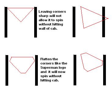
Then using some basic trigonometry for an equilateral triangle, I decided that if the top flat part of the triangle was 12 inches (this being the depth of each control panel), there would be about 3.5 inches of clearance between the top of the panel and the front wall of the cabinet itself at its closest point. This 3.5 inch clearance is plenty for a joystick/trackball/spinner. The concept of this is rather simple, and it really wasn't hard to build and implement. Honestly, I found it harder to do the rotating monitor - and I was copying what Russ did with his Raza's Mame Cab so I had a basic plan to follow, unlike the control panels. The only hard part about the whole rotating control panel thing, outside of coming up with the design, was making sure that the two support triangles that the control panels are attached to, were connected to either side of the cabinet at the exact same spot (see below for details). These two support triangles make the axis for the three panels to spin - if they are off center with each other, the panels won't spin very well. But really, that wasn't that hard - just measured everything about 900 times to be certain it was right before attaching. Below you will see a side view of the rotating control panel idea I came up with. This picture is what you would see if you were standing facing the left side of my cabinet (and if you could see through 3/4 wood!). The support triangles on either side of the cabinet are attached to the side of the cabinet using 4" lazy susans. This allows the traingles to spin freely. With a support triangle on both the right and left hand sides of the cabinet it creates a perfect axis for the panels to spin on. Each of the three control panels is fastened to the same side of each triangle. In the middle of each support triangle I drilled a hole (I matched the size of the hole in the lazy susan - about 1.5 inches). I pass the wires from the control panels through these two holes (1/2 the wires in each hole) and back to the I-Pac and Opti-Pac interfaces. I also routed out a 1 inch wide channel in the sides of the cabinets - starting from where the hole of the triangles are and then back towards the computer about 10 inches - this creates a cavity for the wires to sit in. 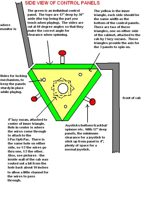
Below is a top view of one control panel - as if you were looking directly down at it. I just provide this to give some clarification on how everything is situated. You see that each control panel is attached to the support triangles using machine bolts. This makes it quite simple to remove a panel to work on it, yet when attached keeps the panel very secure to the triangles. Also, you'll see that on either side of the cabinet I have a eye bolt which screws in through the cabinet to a inside nut attached to the triangles. This is what keeps the triangles steady when playing on of the control panels. More information is below, but to switch panels you simply unscrew both eye-bolts, spin the panels to the one you want, and then screw the eye-bolts back in. It may not sound sturdy, in fact I was planning on using a total of four eye-bolts, but after installing the first two it was incredibly sturdy. There is no play at all in the panels, they don't move a bit even with months of some serious game playing. 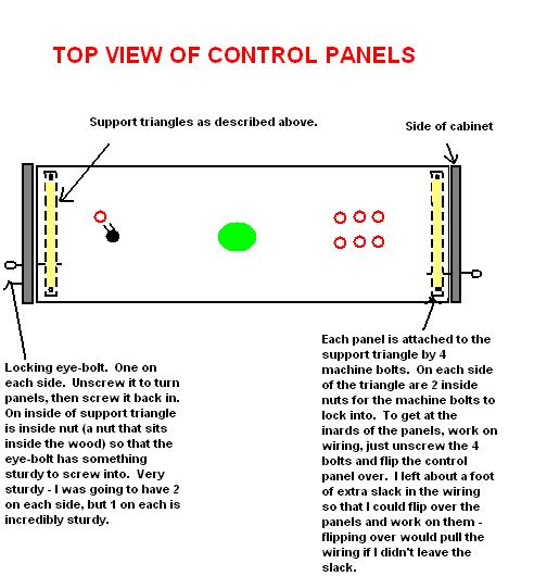
On to the 3 Panels page for details of the three panels. Feel free to email me at doug@dgthompson.com |
|