
I am building a new website that you can visit HERE
You can email me at doug@dgthompson.com
This is an incredibly low level, simple web page just to show my brother who live 1000 miles from me my progress. Once the cab is complete, I'll turn my time to playing it 20 hours a day.... er... I mean, creating a real website.
The Idea: Since I stumbled across Mame in 1999, I've wanted to build a cab. For 3 years I kept coming up with plans and ideas and kept putting them off. In December of 2002 I finially got off my butt and started to build (I also have 3 small kids which take up 140% of my time, so finding time is tough). In my 3 years of thinking and planning I decided I had to have a rotating monitor AND control panel. While all the control panels out there I looked at are great, I wanted to be able to have seperate control panels for 1 plyer games, for 2 player games, as well as one specific to some of my favorite games - Defender and Asteroids. Rotating is the way to go.
For the monitor I struck up an email conversation with Russ who made Russ's Mame Cab( his site appears to be down). I love his simple yet very effective design. I modeled my spinning monitor after his.
For the spinning control panel I was on my own since I couldn't find anyone else that had made one (I have since discovered 1UP's Arcade, he has another type of spinning control panel design which is great as well). Having a 45 minute communte to work gives me allot of time to think... I thought that the best idea was to go with a triangle. A triangle, while it spins on it's axis, gives you enough space for the controls to fit without hitting the walls of the cab. A triangle is also very easy to make, and if you have some knowledge of trigonometry you can easily figure out the angles. I quickly realized in my prototypes that you need to flatten the corners of the triangle, making a "superman shape" design. The superman shape allows the triangle to spin without it's corners hitting the inside walls of your cab. You basically have an equillateral triangle (all corners 60 degrees), flatten the corners, and you are set. The depth of each panel (from the monitor to your waist) needs to be long enough to allow enough gap for the jopysticks to fit through. I've gone with a 12 in depth. Fairly common depth (there are allot of games with a shorter depth, though in my studies and hours at the arcade, 12 inches was pretty normal as well).
I am done with my spinning control panel but need to post much better pictures, but for now here is an incredibly low level and ugly design of the SIDE VIEW of the control panel I came up with about 2 weeks after I discovered MAME in 1999. Not drawn to scale, but you can get the idea.
SIDE VIEW
top of cab (monitor side)
 front of cab
bottom of cab.
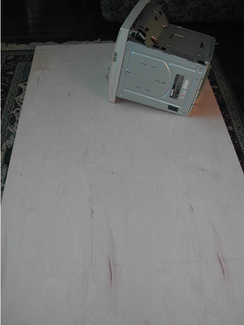
It begins....
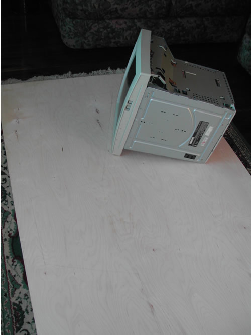
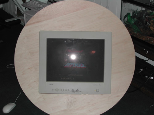
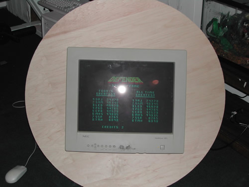
Getting the monitor the correct angle to my own eyes which are 5'6" from the floor (I am 5'11"). I actually laid down on the floor next to it to mark my eyes, get the monitor perfectly perpendicular to my eyes, hooked it up and watched Defender go through it's demo game just to make sure all looked good!
F*cking 25 degrees out!
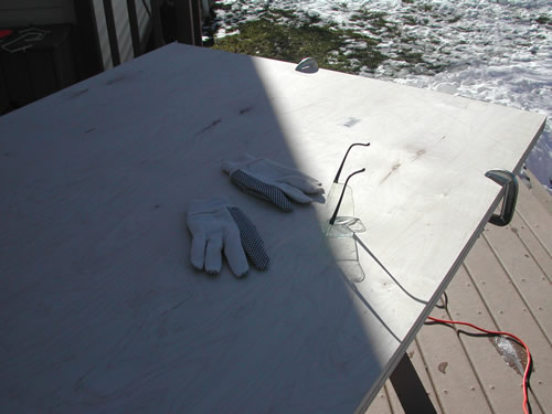
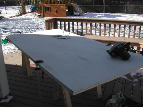
I'm ready!
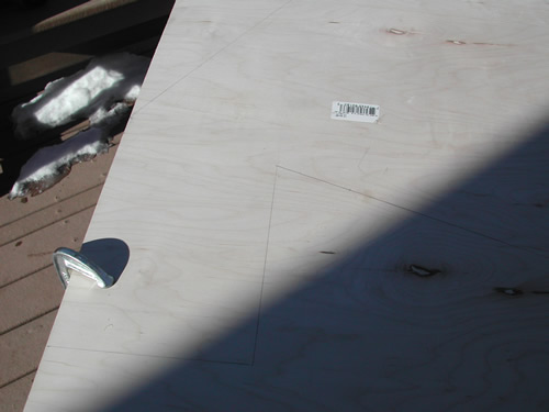
Outlines drawn, ready to cut
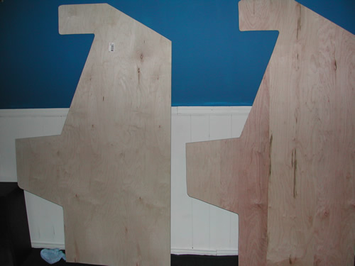
Twins!
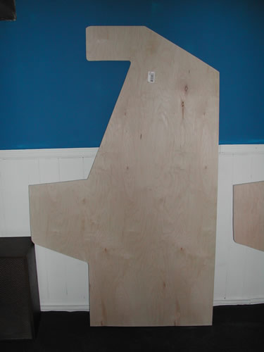
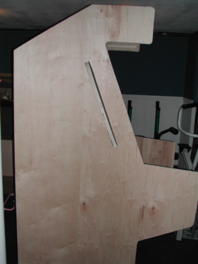
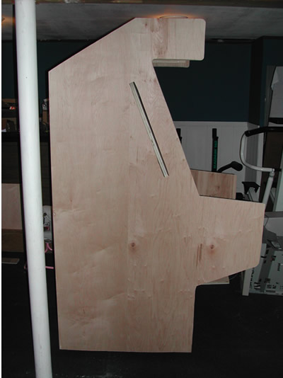
Profile
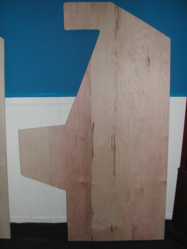
Profile
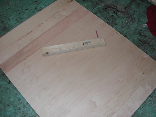
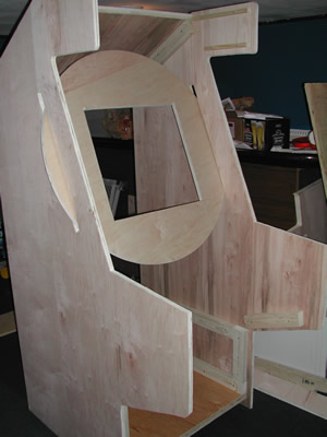
Look at the monitor wheel circlebr>
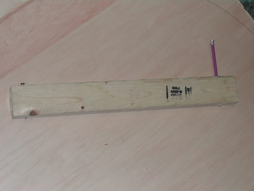
My circle drawing tool!
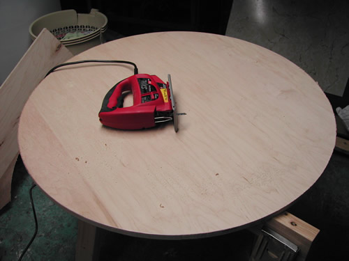
over 1 hour to cut this by hand - came out f*cking perfect!
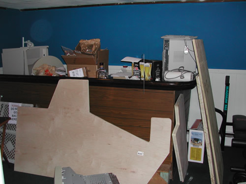
Basement used to be neat.
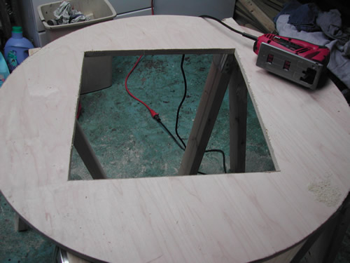
Cutout for monitor - took 1 hour to measure exactly center
Monitor in Wheel
Perfectly centered!
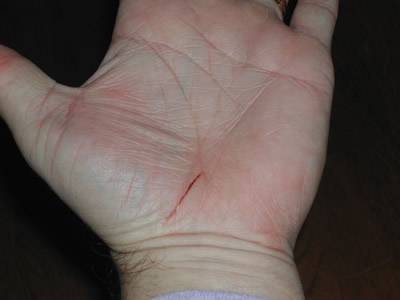
First big injury - from metal monitor casing. Bled for about 20 minutes, freaking my son out!
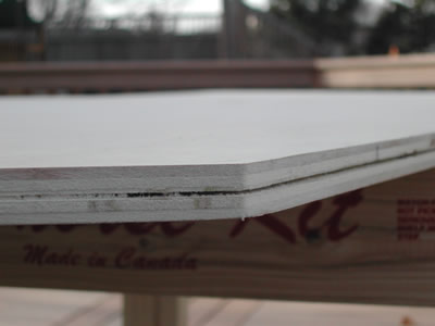
T-Molding routed - cut like butter!
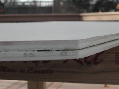
Edge - closeup
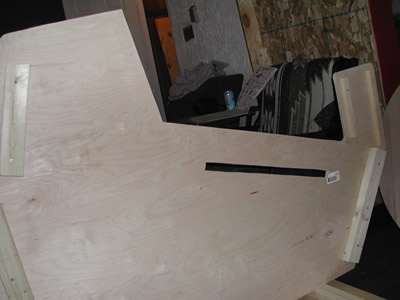
Inside - slot for monitor wheel
Inside - you can see some of the skeleton
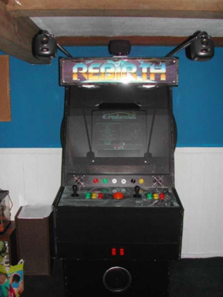
Holy Shit, it is starting to look like a Cab!
Profile Closeup
Profile - can't see it but about 3/4 inch gap on bottom from wheels
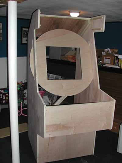
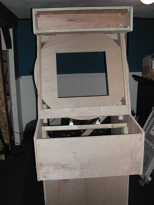
Front view with Keyboard drawer closed
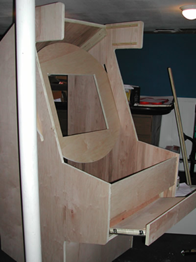
Keyboard drawer open
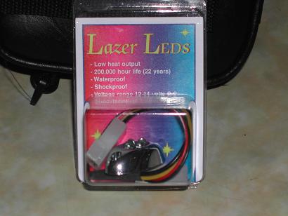
For my translucent Trackball, I found this cool thing that is really made for motorcycle lights
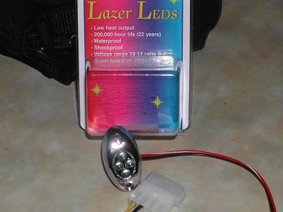
4 Super-Brite LED's. I plugged this into my PC and it just about blinded me it is so bright
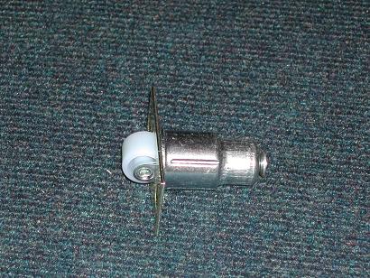
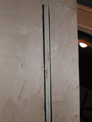
I just happened across this at Home Depot. That white wheel is on a strong spring, so it pops in and out. This is installed pressing in against the montior wheel, then when you spind the monitor wheel I have holes/stops at perfectly vertical and horizontal - so the white wheel will pop out, stopping the monitor at the perfect spot
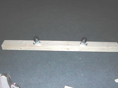
Example of some of the wheels the monitor wheel will rest against, allowing it to spin freely.
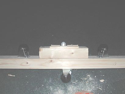
Here is the part of the support wheels with the spring wheel "stop" thing in place
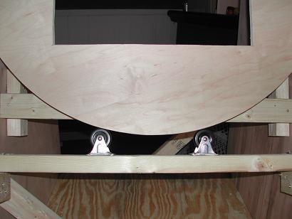
Closeup of the bottom edge of the monitor wheel resting on 2 caster wheels
Some of the back support wheels. There are 9 wheels supporting this baby, 2 on the bottom edge, 2 behind the top, 3 behind the bottom (including the pop-up wheel), and one behind the left side and one behind the right side.
More wheels
I love wheels
A full view of the back of the monitor wheel - you'll see the wood on top, bottom and 2 sides which the wheels are connected to
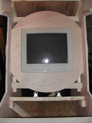
I couldn't wait - I threw the 95 pound montior in and spun the thing in about 20 360 degree circles.
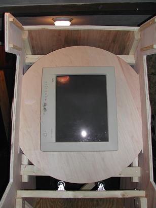
Here is the monitor vertically. The thing spins very easily and the way it is set up it is impossible not to stay in it's track. It dosn't spin like a well lubed bicycle tire, but easy and free enough that my 4 year old was able to do it with no problem. Once I add the t-molding to the edge of the monitor wheel it should spin easier than an alcoholic's head after binge drinking. Notice the screen is perfectly centered in each position. Taking 2 hours to measure an cut that out perfectly paid off.
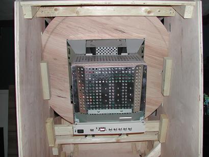
Back view. It sort of looks like the bottom of the monitor is resting on 2x4's, but it isn't. I didn't even screw the montior to the wheel yet and it feels perfectly sturdy - amazing really
check out the wheel perfectly centered in the slot.
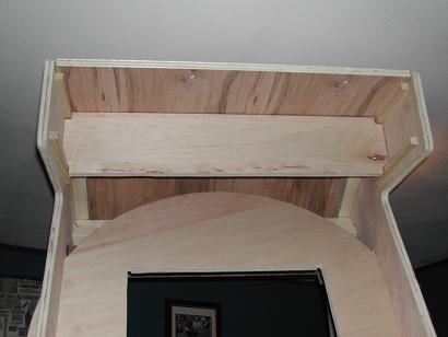
Where the marquee lighting will go (I bought 2 24 inch flourecent fixtures to really light up the marquee)
All the wood done and installed - just ned the control panel
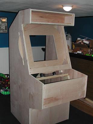
Side view... getting excited
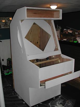
After 2 coates of primer, sanding in between
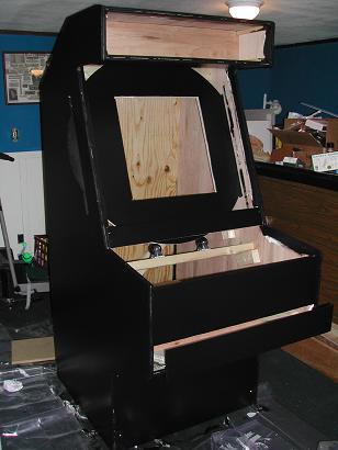
After 2 coats of paint, sanding in between
Black paint looks awesome. After I add the side art I plan on adding a few coats of poly-crylic to really protect everything and make it as shiny as a baby's ass.
ROTATING CONTROL PANELS
I always liked the idea of having different control panels instead of trying to put all the different controls I wanted onto one big control panel. I originally thought of having swappable panels, with quick contector blocks - but thought that the best way to accomplish this was to have rotating control panels that I could spin to whichever one I needed for a given game. I decided that the best way to have a rotating panel was to use a triangle design with 3 control panels (a square design with 4 panels wouldn't give enough clearance for the controls to pass by the sides of the cabinet - though since I built this I did think of a way to possibly do this, email if you care).
I sat down with a pad of oversized paper and tried out different designs by cutting them and spinning them on their axis. It wasn't long before I realized that the triangle needed to have flattened corners, similare to the shape of the Superman logo. If you cut out a triangle and spin it you'll see what I mean, leaving the pointy corners will not work. See my wonderful graphic to show this:

Then using some basic trigonometry for an equillateral triangle, I decided that if the top flat part of the triangle was 12 inches (this being the depth of each control panel), there would be about 4 inches of clearance between the top of the panel and the front wall of the cabinet itself at its closest point. This 4 inch clearance is plenty for a joystick/trackball/spinner. The concept of this is rather simple, and it really wasn't hard to build and implement. Honestly, I found it harder to do the rotating monitor - and I was copying what Russ did with his Russ's Mame Cab. The only hard part about the whole rotating control panel thing, outside of coming up with the design, was making sure that the two support triangles that the control panels are attached to, were connected to either side of the cabinet at the exact same spot (see below for details). These two support triangles make the axis for the three panels to spin - if they are off center with each other, the panels won't spin very well. But really, that wasn't that hard - just measured everything about 900 times to be certain it was right before attaching.
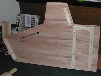
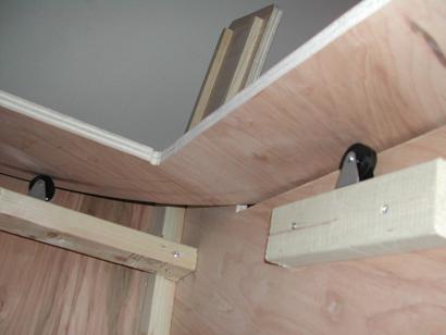
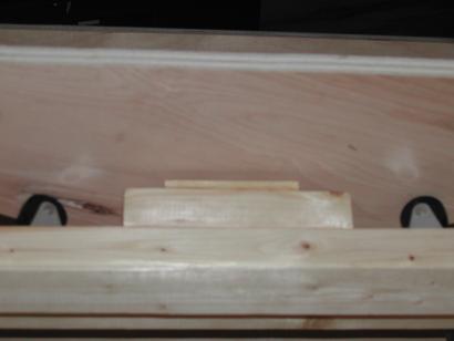
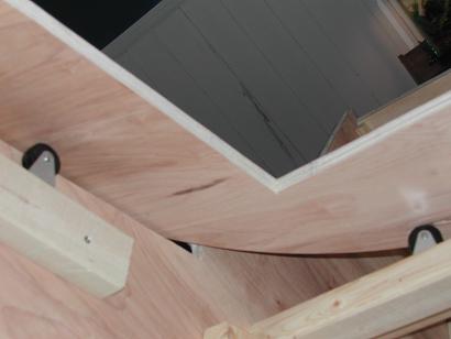
Below you will see a side view of the rotating control panel idea I came up with. This picture is what you would see if you were standing facing the left side of my cabinet (and if you could see through 3/4 wood!). The support triangles on either side of the cabinet are attached to the side of the cabinet using 4" lazy susans. This allows the traingles to spin freely. With a support triangle on both the right and left hand sides of the cabinet it creates a perfect axis for the panels to spin on. Each of the three control panels is fastened to the same side of each triangle. In the middle of each support triangle I drilled a hole (I matched the size of the hole in the lazy susan - about 1.5 inches). I pass the wires from the control panels through these two holes (1/2 the wires in each hole) and back to the I-Pac and Opti-Pac interfaces. I also routed out a 1 inch wide channel in the sides of the cabinets - starting from where the hole of the triangles are and then back towards the computer about 10 inches - this creates a cavity for the wires to sit in.

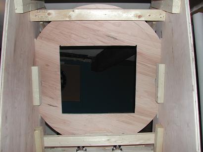
Below is a top view of one control panel - as if you were looking directly down at it. I just provide this to give some clarification on how everything is situated. You see that each control panel is attached to the support triangles using machine bolts. This makes it quite simple to remove a panel to work on it, yet when attached keeps the panel very secure to the triangles. Also, you'll see that on either side of the cabinet I have a eye bolt which screws in through the cabinet to a inside nut attached to the triangles. This is what keeps the triangles steady when playing on of the control panels. More information is below, but to switch panels you simply unscrew both eye-bolts, spin the panels to the one you want, and then screw the eye-bolts back in. It may not sound sturdy, in fact I was planning on using a total of four eye-bolts, but after installing the first two it was incredibly sturdy. There is no play at all in the panels, they don't move a bit even with some serious game playing.

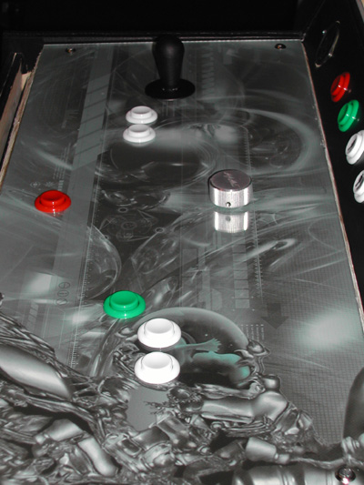
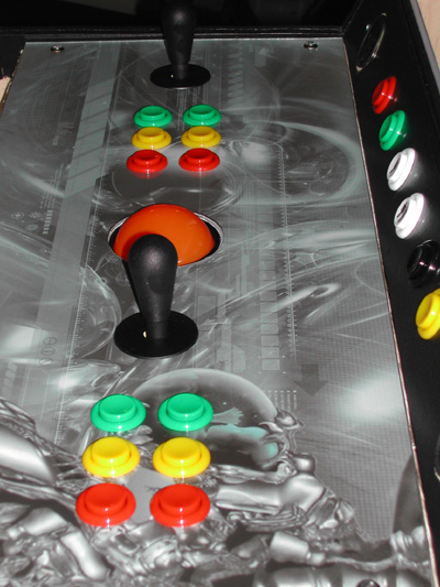
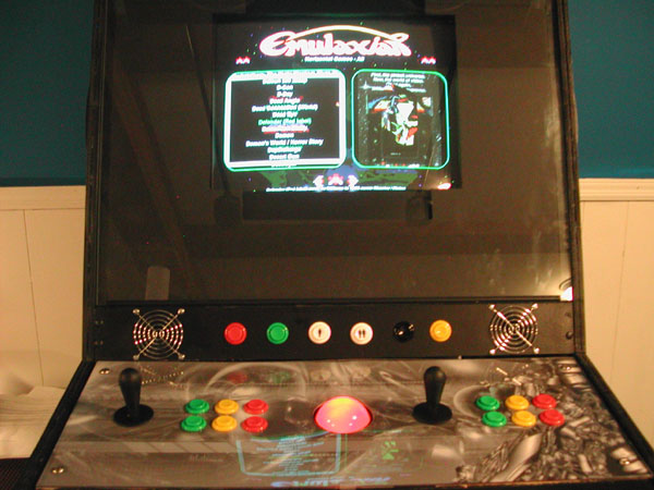
CONTROL PANEL #1
So now I have three panels, what to do with them... The whole reason I even found out about Mame back in 1999 was when I was surfing the Net looking for sites with my all time favorite game - Defender. So I decided to have one control panel be a replica of the Defender control panel - since the Defender controls were much different that almost every other game out there, I wanted a panel to emulate that. I installed a Happ Ultimate 8 way joystick and an Oscar Controls 2 way restrictor so that it would only go up and down (easier than trying to find a good 2 way stick). Another favorite, Asteroids, has a very similar control panel, so I added one button next to the Defender "reverse" button so that the panel also matched the Asteroids layout. This extra button for Asteroids also acts as the "Inviso" button for Stargate, the sequel to Defender (which in my eyes doesn't live up to the Defender excellence much. This "inviso" button isn't in the correct spot, but it is in a spot I think is much better than where Williams put it, below the smart bomb button...). I also added an Oscar Pro spinner to this panel since it didn't get in the way with Defender/Asteroids and I needed to put it somewhere.
CONTROL PANEL #2
The second control panel is a standard one player control panel. I installed a Happ Ultimate 8 way joystick on the left and 6 Happ buttons on the right. In the middle I installed a Happ Ultimate 8 way with an Oscar Controls 4 way restrictor plate - for 4 way games like Pac-Man. Again, you can buy 4 way joysticks, but found it easier to by a known great joystick in the Happ, and add the restrictor plate which works great.
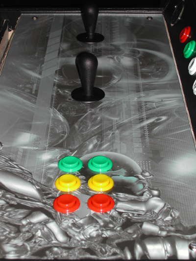
CONTROL PANEL #3
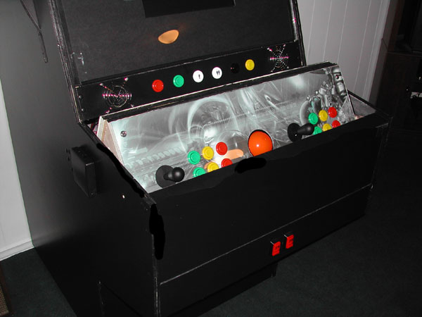
The third panel is a standard two player panel. I installed 2 Happ Ultimate 8 ways, each with 6 Happ buttons next to it. In the middle I added a Happ 3" Highball trackball (translucent red - lit underneath by 4 superbrite LED's). This allows simultaneous 2 player games (i.e. Street Fighter), 2 joystick games (i.e. Robotron) and trackball games (i.e. Missile Command). Note: These pictures are before the bezel and side art were added.
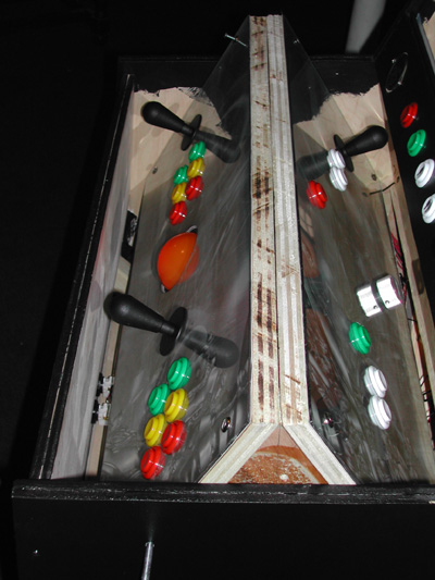
CONTROL PANEL SPINNING
Here are some pictures of the control panel spinning, halfway between the two player panel and the defender panel.
INTERFACE
All of the joysticks & buttons are wired to a Ultimarc I-Pac. You can wire more than 1 item to the same input on the I-Pac. For example, I have 5 joysticks total in the cabinet and 4 of them are wired to the player 1 joystick inputs of the I-PAC (the 5th joystick, that being the player 2 joystick on the 2 player control panel is wired to the player 2 joystick input of the I-Pac). Since I am only using one of the 4 player 1 joysticks at any time, there is no conflict. So if I go left on a player 1 joystick, the I-Pac just gets 1 Player 1 Joystick Left signal even though there are 4 joysticks connected to that (see the wiring page for much more details). You could have 100 panels all wired to the I-Pac and it would work. The Oscar spinner and Happ trackball are both wired to an Ultimarc Opti-Pac. Both Oscar and Ultimarc make incredible products.
ROTATING CONTROL PANELS - CONSTRUCTION
STEP 1: After making the plans and making mock-ups with paper and assuring myself that it would work, I got down to cutting the wood. The first part I cut was the three control panels. All three panels were made the same way. The way I did it was to cut the wood 29 7/8 inches wide (the inside of my cabinet is 30 inches wide, so I left a 1/16 gap on either side of the control panels so they could spin easily). I then made two lines across the top of each panel 12 inches apart (the "top" being the part you see or the part your hands rest on when playing a game). The top of the panel needed to be 12 inches so that when spun, there would be at least 4 inches clearance for the joystick to pass the front of the cabinet. The front and back of each panel needs to be tapered at 60 degrees. This will create the flattened corners, like the Superman logo as described above. I set my table saw blade at 60 degrees and cut the sides of the panel length-wise on each line I drew. The bottom of the panel will be larger than the top of the panel, so make sure when cutting you have the table saw angled in the right direction.

Blank control panel after cutting. You see the top of the panel here.

Side view. Make sure the top is 12 inches wide and the bottom is inches wide
STEP 2: Now that I had all three panels cut, it was time to cut the support triangles. Make sure the length of each side of the triangle is the same as the depth of the bottom of each control panel ( inches for my cab). Each corner of the triangle has to be 60 degrees, so that each side of the triangle is exactly the same. Also, I wanted my support triangles to be sturdy, plus I needed some thickness to put the insert bolts into the sides where the panels would bolt into - so I made each triangle out of two triangles attached together (double thick). These triangles are normal looking triangles with pointy corners. When the panels, with their tapered corners, are attached the corners will then have the flattened shape.

Two 3/4" thick triangles (I made 4 total). These were then glued together to make one thick triangle (two total). One is full of dried glue after a glue mishap cause by my cat.

Two 3/4" triangles glued together. Look closely and you'll see the lines drawn from the middle of each side to the point of the oposite side. Where they intersect is the middle of the triangle.
STEP 3: I then cut a hole in the middle of each support triangle, a hole to match the hole in the lazy susans which will be attached.

4" lazy susan (need two of these, one for either side)

Support triangle with hole in the middle.
STEP 4: I then attached a lazy susan to the middle of each support triangle. This can be a bit tricky to think about, if you have ever worked with lazy susans you probably know... Attaching the lazy susan to the support triangle is easy, just make sure it is centered (easy way is to make sure the hole in the lazy susan is centered over the hole in the triangle). The tricky part is thinking of how to then attach the other half of the lazy susan to the side of the cabinet. What I did was after I attached the lazy susan to the triangle, I marked off where the screw holes were for the other side of the lazy susan (just spin it a bit). I then drilled a big enough hole for a screw driver to fit through at each hole point. Then when attaching to the cabinet, I just stick a screw and a screwdriver through these holes and screw the 2nd side of the lazy susan to the side of the cabinet. See pictures for details.

Lazy susan attached to support triangle (ignore the red paper for a second)

4 holes drilled where lazy susan screw holes are, for screwdriver to fit through