

|
|
ROTATING CONTROL PANEL - Construction - STEP 1 Here I go into the details regarding the construction of these panels. I am going to refer to the finished product as a control panel "contraption". This contraption can then be attached to the inside of a cabinet. I've been asked many times to provide details of this, so I am including a lot of information here - I apologize if it may get too wordy! CONCEPT As explained earlier, after much thought, I came up with the plan to have a triangle design with flattened corners. This design was a very simple design and allowed for the panels to rotate without much effort - just remove the locking mechanism, spin, relock. I explained in detail why I flattened the corners of this design back on the overview page so I won't restate it here. This is the concept picture again: 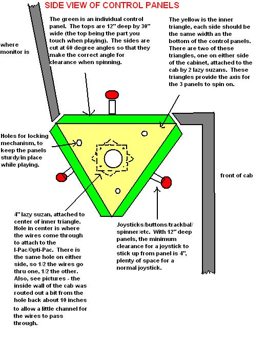
MEASUREMENTS/CUTTING - Control Panels The width of the control panels was dictated more by the rotating monitor - the cabinet had to be wide enough to allow the monitor to rotate - but the width is also fairly standard for a 2 player cabinet (it is wide enough to allow two people to stand side-by-side comfortably). I went with a width of 30 inches. The depth of the panels was more my choice. Through various paper designs and a bunch of high school trigonometry I decided that a 12 inch depth would be good. 
With my rotating design, the deeper the panel, the more clearance you have when rotating, hence the taller control you have have on each panel. With my design and a 12 inch deep panel it leaves you with a maximum clearance for the controls of 3.5 inches. So I can have controls up to 3.5 inches in height. For reference, my tallest controls - the joysticks - are only 3 inches in height from the surface of the control panel (the joystick is taller than that, but much of it lives under the surface of the panel, only 3 inches sticks up from the surface). If you wanted a taller control then you can just make the panel deeper to gain more clearance. When cutting these panels, you must cut the long sides (30" sides on mine) at a 60 degree angle from the top of the panel (see "side view of conrol panels" image above). Cutting them at this angle provides the correct shapped "corner" so that when they are spun they do not hit the cabinet - yet provides extra room inside the panels for your controls/wiring. I do not think you have to cut these at an exact 60 degree angle, but you should try and get as close as possible. An easy way to get to this angle is to cut out an equilateral triangle shape on a peice of paper (any size), then fold a corner down evenly (so that the corner is "flat" like in my diagram above). The angle created by that folded corner is 60 dgrees - just hold that up to the side of your wood and draw a line to cut on. I used a table saw with a blade angled at 60 degrees myself (though I did draw that 60 degree line to be certain). Cut all three panels out. You are on your way to a Mame machine now! MEASUREMENTS/CUTTING - Triangle Axis's The key to my rotating design are the two side triangle axis's, so the measurements of these must be done carefully. Each side of the triangle must be the same length as the bottom of your control panels. Just measure the bottoms of the control panels (they should all be the same if you cut them well), and make that the length of your triangle sides. Now you need a triangle axis on the left and right sides of your rotating panel contraption. You need sturdy triangles, so each of my triangles is actually 2 triangles cut from 3/4 inch wood glued/screwed together. This allowed them to be thick enough (1.5 inch thick) to attach the panels to more easily (more on that later). So cut 4 triangles out of 3/4 inch wood, and glue/screw 2 sets of them together. FINAL PREPARATION - Triangle Axis's / Panels Do the following for each triangle: Center a lazy suzan on one side of the triangle, and then trace out the hole in the middle of the lazy suzan onto the wood. Remove the lazy suzan and drill a hole through the triangle as close to the size of that traced hole that you can (this hole is to allow the wires to pass through). Once the hole is cut, attach the lazy suzan to the side of the triangle. Take your time, make sure the lazy suzan is perfectly centered. When you are done you will have 2 triangles, each with a hole in the middle and a lazy suzan attached to the sides. Do the following for each triangle: The lazy suzan is made of up two metal plates. Spin the plate is not screwed to the wood triangle such that the corner screw holes clear the other plate (so you can look through the screw hole and see the side of the wood triangle). Carefully marke off on the wood triangle where each of the 4 lazy suzan screw holes were. Drill a hole through the wood triangle at each of those four screw hole markings - make the hole large enough so that the head of the wood screw that will be used to attach the lazy suzans to the side of the cabinet will fit through. If you haven't figured it out already, since one side of the lazy suzan is already attached to the triangle, you need these holes in order to screw the other side of the lazy suzan to the side of the cabinet. Do the following for each triangle side/control panel: You are now almost done getting the control panel contraption ready. you are going to attach the control panels to the triangles using bolts and T-nuts (search homedepot.com for "t-nut" if you do not know what these are). You need to drill a hole near each corner of the control panel, where 4 bolts will pass through to bolt into the triangle. You first need to figure out where to drill these holes. You'll want to drill each about 2 inches in from the long sides of the control panel. How far in from the short sides of the panels depends on the width of your trangles and lazy suzans. You do not really want to have the short sides of the control panels flush with the side of the triangles. If you do this, the lazy suzans will stick out the sides of the control panel contraption. You'll want to "indent" the trangles the amount of the thickness of your lazy suzans (when looking at the side of them) so that the outter side of the lazy suzan is flush with the short side of the control panels. So if your lazy suzans are 1/4 thick, you will want to indent your triangles 1/4 inch. So you want to drill your bolt holes in the width of your lazy suzans + half the width of your triangles. In my case, my lazy suzans were 1/4 inch thick, and my triangles were 1.5 inches thick - so I drilled my bolt holes 1 inch in from the short sides of the control panels (1/4 + 3/4). This way the bolts will go into the middle of the triangles when the triangles are indented 1/4 inch. OK, drill the 4 holes in each panel now - the hole size based on the size bolts you bought. It is best now if you mark each panel with a 1, 2 and a 3 respectively, and for each mark one side as "left" and the other "right". Now mark each side of the 2 triangles with a 1, 2 and 3 respectively. mark one triangl as "left" and the other "right" You now need to mark where your bolt holes are for each panel, onto the edges of each triangle. For example, hold the "left" triangle , side #1 under the "left" side of panel #1. Make sure it is indented as described above and mark off where the two bolt holes are. Do the same for the right side of panel #1 on the "right" triangle (side "1"). Now the the same for the other 2 panels and corrsponding sides of the triangles. Now drill a hole and hammer in the t-nuts where each of these bolt hole markings were. To make it extra sturdy, I also put some epoxy glue in each hole before inserting the t-nut. Do not do it now, but if all was done correctly you would be able to attach the 3 control panels to the 2 triangles now and have a finished control panel "contraption". On to the Panels Cunstruction - Step 2. Feel free to email me at doug@dgthompson.com |
|